909 Sound Mods
DISCLAIMER: All modifications are carried out at your own risk.
If you're not sure which end of a soldering iron to hold, get someone else to hold it for you.
READ THESE INSTRUCTIONS COMPLETELY BEFORE YOU BEGIN !
909 Bass Drum Mod - Enhanced Version
Here's an updated verion of my 909 bass drum mods, that will give you a considerably more flexible bass drum. The original 909 bass drum has 4 controls:
Level - controls the volume (duh)
Tune - controls the decay time of a short falling pitch envelope
Attack - controls the level of an initial noise burst and click
Decay - controls the length of the bass drum
The following mods extend the range of the Tune and Decay controls, and add three new controls:
Pitch - controls the frequency of the bass drum oscillator
Drive - allows waveform adjust from normal to square, for hard clipped sounds
Tune Depth - varies the amount of initial pitch sweep (decay set by TUNE control)
First I'll detail the extended ranges for existing controls. These mods can be performed without removing the 909's voice board.
Place the 909 face down on a surface that won't scratch it, with the connectors facing away from you. Remove the bottom panel.
Extended Decay Mod
This mod extends the maximum decay time of the kick significantly.
Take a look at the bass drum schematics (scanned by R@F)
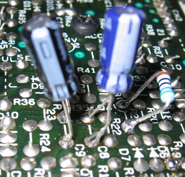
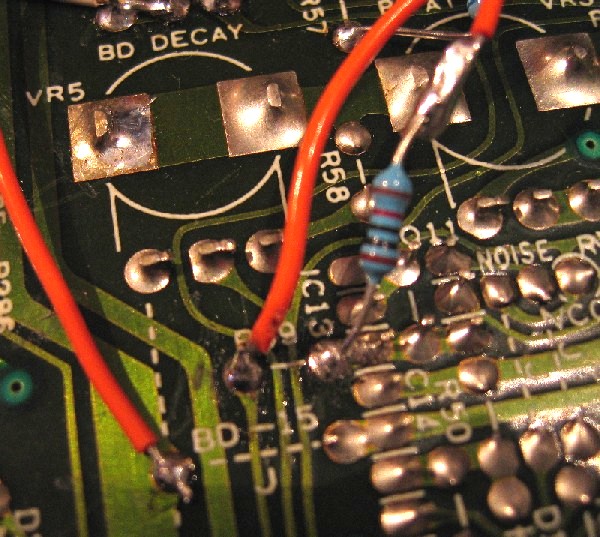
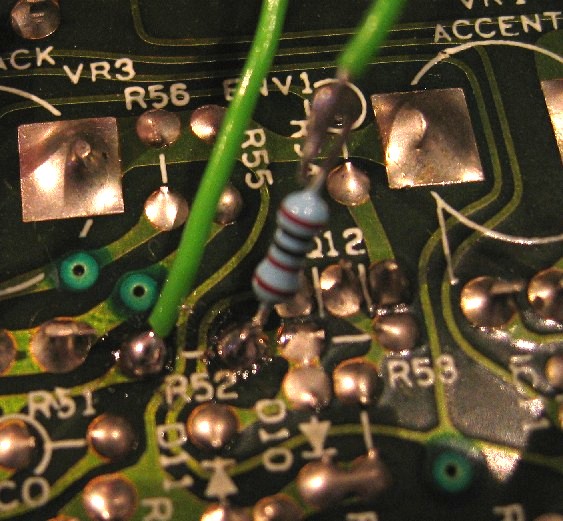
The amplitude decay curve (ENV 1) is provided by capacitor C8, which is charged up when the drum is triggered via D9, and discharges through VR5 and R58. The voltage on C8 controls the VCA - Q12. To extend the decay range, we just need to increase the size of C8, which we can do most easily by adding another capacitor in parallel with it. I found 1uF a good choice of value. The following photo shows the new capacitor in place (it's the one in the middle), as well as the extra capacitor and resistor for the extended Tune range mod described below.
Tune Control Extra Range
The Tune control is really a decay control for a simple envelope generator that provides the intial falling pitch sweep on the bass drum oscillator (ENV 3). The standard range is very narrow - from around 30 to 120 milliseconds. The voltage on capacitor C9 indirectly controls the oscillator pitch. It is charged via D7 and R21 when the drum is triggered, and discharges through R57 and VR2. Since we can't easily change the value of VR2, to extend the maximum tune decay time while keeping the minimum time the same and also making sure we don't change the fixed attack time of the sweep, we need to change the values of R21, R57 and C9.
I added an extra 1uF in parallel with C9, added 560 ohms in parallel with R21, and 6.2k in parallel with R57. This is equivalent to increasing the size of C9 by 4 times - the extra resistors roughly quarter the values of R21 and R57. This makes the decay time if VR2 is at minimum the same as it would be before, but makes the maximum decay time 4 times longer. R57 isn't shown in the photo above - it's hiding up next to the attack pot.
The Extra Controls
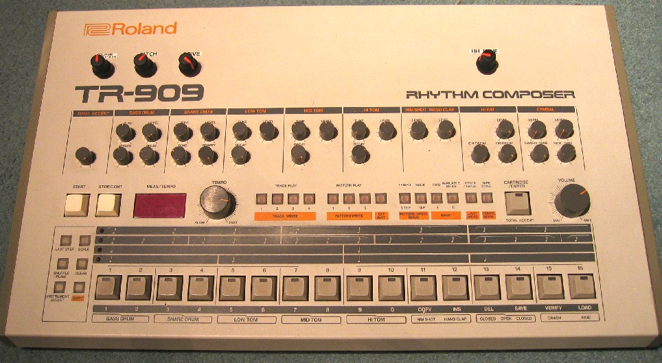
If you want to add the three extra controls, you can either drill holes in the plastic side panel to make the new knobs discrete, or drill new holes in the 909 front panel. Here's a 909 I've modded:
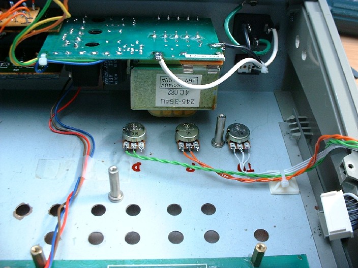
And here are the locations of the Drive, Pitch and Tune Depth pots behind the front panel:
Please don't attempt to drill holes in your 909 unless you're entirely confident in your ability not to screw it up, or 'mint condition' means more to you than 'much more versatile bass drum' !
If you are fitting the pots to the front panel, you should solder wires onto them long enough to reach round the side of the voice board when it is re-fitted.
Pitch Control
This mod adds a pitch control to the bass drum oscillator.
A 100k linear pot and 10k resistor are soldered in, in series, to *replace* the original resistor R59. The 100k pot is the middle of the three in the photo above. Note the pins the two wires are soldered to.
First, you'll need to remove R59. If you are doing this without removing the circuit board, use a solder sucker or desoldering braid to desolder the resistor so that it falls out of its holes, then let it fall out of the bottom of the case.
Trim the leads on the 10k resistor so they are about 10mm long, and solder one end to one of the pads where R59 was removed (it doesn't matter which one).
Then solder one wire from the 100k pot to the other pad on the pcb, and the other wire to the end of the 10k resistor.
Drive Control
This mod alters the clipping circuitry that rounds off the triangle wave from the VCO to create a more sine-like wave. It's possible to 'overdrive' the diodes used to create the sine wave to allow much squarer waves to be produced. This gives an effect similar to an overdriven mixer channel, but without any added noise, level changes, or crosstalk between mixer channels.
The mod is carried out in the same way as the tune mod - a fixed resistor is replaced with a pot and another resistor in series.
In this case, it is resistor R52 that is replaced, by a 10k pot and a 1k resistor in series. Apart from that, the mod is the same as the pitch control mod above. R52 is marked on the silkscreen. It is just below and to the left of the attack pot. The 10k pot is the one on the left of the photo above.
The wiring at the PCB should look something like this:
Tune Depth
If you refer back to the schematic, you'll see the Tune envelope (ENV 3) generated on C9 passes through IC12A before it reaches what is essentially a control voltage input for the oscillator at the junction of R29 and R31.
This voltage can't fall to 0v, or the oscillator would cut-out altogether. So R27, the 1.5M resistor at the negative input of IC12A, adds a fixed voltage offset to the output of IC12A which sets the minimum frequency of the oscillator. This means we can't vary the tune depth just by putting a potential divider between the output of IC12A and the oscillator control input, or by making the gain of IC12A variable.
To get round this, I removed R27, and restored the effect of the offset voltage at the CV input with a pair of 1Meg resistors to both the positive and negative inputs of IC12B - at the other ends of R29 and R31. These 1M resistors come from the -15v supply.
This alters the circuit so that IC12A is providing an envelope voltage that now falls all the way to 0v. So we can change the amount of pitch sweep with a potential divider, or by making the gain of IC12A variable (replace R28 with a pot). I used a 10k pot as a potential divider, as I didn't have a suitable pot to replace R28 (the gain setting resistor of IC12A).
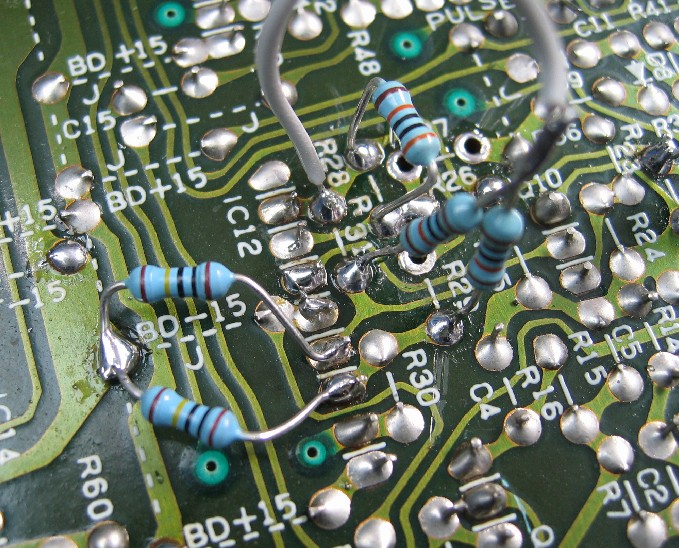
To break the link between the output of IC12A and the oscillator control input, I removed the two resistors R29 and R31, and replaced them with new resistors of the same value soldered to the pads by one lead each, and then connected together by their other.
This photo shows all the Tune Depth mod resistors in place.
The wire to the now separate CV input (the connected leads of the replaced R29 and R31) comes from the wiper of the tune depth pot (10k). The wire from the clockwise end of the depth pot connects to the other pad R31 was removed from, i.e. the output of IC12A.
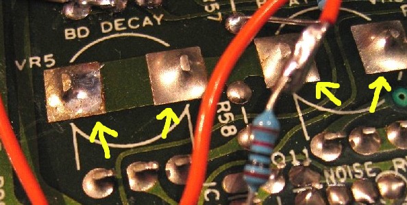
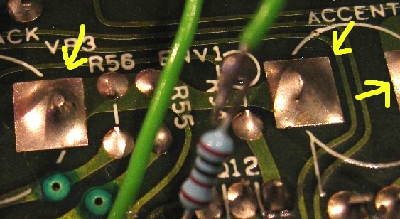
The third and final wire from the other end of the pot connects to 0v / ground. I solder this to one of the standard pot shields, which can be seen in the photos showing the pitch and drive mods, but for clarity I've indicated these with arrows below. You can make the 0v connection at any of these points:
To increase the maximum amount of sweep, I then increased R28 from 150k to 300k, by removing the original resistor and soldering a new one to the pads. This increases the gain of IC12A, and doubles the maximum amount of sweep. If you set the new tune depth control to halfway, you'll get the same amount of sweep as the original fixed level. The alternative would have been to leave R29 and R31 in place, and then add a 300k pot as a variable resistor in place of R28.
Here's a quick mp3 demo of the new and extended bass drum controls being tweaked.
909 Hi-hat Tune
This mod gives a tune control for the hi-hats that functions the same way as the tune controls for the crash and ride cymbals. You'll need a 6k9 resistor, a 22k linear pot and some more wire.
The mod is very similar to the bass drum tune mod, except this time the resistor to be replaced is R492. This is located at the far left, near the front of the pcb:
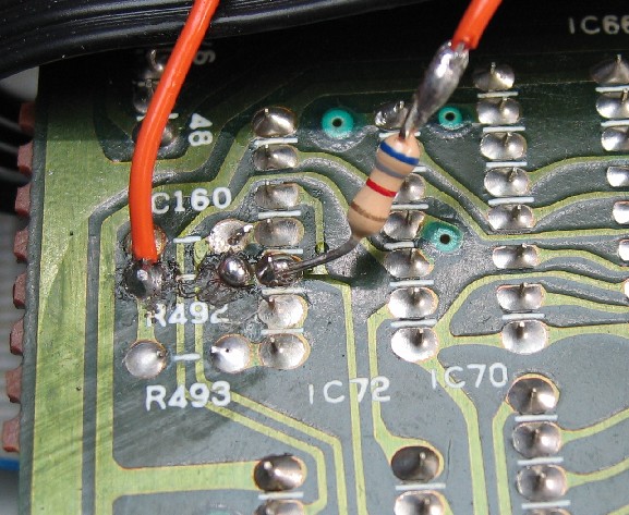
Note that the resistor above is soldered to the IC pin rather than the pad of R492, as this unit has been taken apart and re-assembled so often, the pad came off.
Remove the original resistor as before with a solder sucker or braid.
Trim the leads of the 6k9 resistor to 10mm and solder one lead to one of the pads where R492 was located.
Cut two lengths of wire, solder one to the resistor, one to the other pad of R492, and then solder both of the other ends of the wires to the 22k pot, or solder the wires to the pot first if you need to mount the pot to the front panel before re-fitting the voice board.
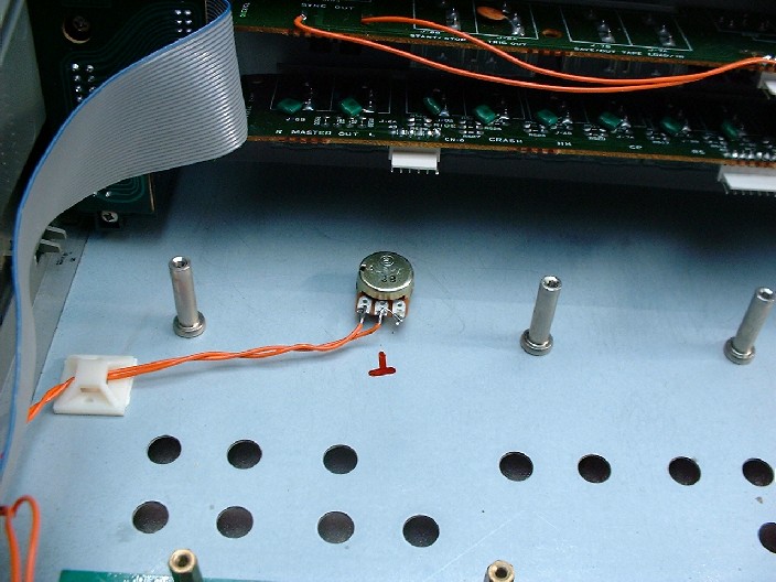
Here's the location of the Hi-Hat tune pot I added to the front panel of the 909 above:
Enjoy !

Last update: 18th May 2004
home